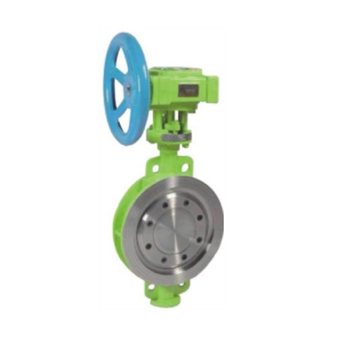
How to Calibrate Stop Valve Actuators
Introduction
Stop valve actuators are critical components in industrial and commercial fluid control systems, ensuring precise regulation of flow, pressure, and isolation of pipelines. Proper calibration is essential to maintain accuracy, reliability, and safety in valve operation. This guide provides a comprehensive step-by-step procedure for calibrating stop valve actuators, covering mechanical, electrical, and pneumatic types.
---
1. Understanding Stop Valve Actuators
Before calibration, it’s important to understand the different types of actuators:
1.1 Types of Actuators
- Electric Actuators: Use electric motors to control valve movement.
- Pneumatic Actuators: Operate using compressed air or gas.
- Hydraulic Actuators: Utilize pressurized fluid for movement.
- Manual Actuators: Adjusted by hand (not covered in calibration).
1.2 Key Components
- Positioner: Ensures the valve reaches the desired position.
- Feedback Mechanism: Provides real-time position data.
- Control Signal: Typically 4-20 mA or 3-15 psi for automated actuators.
---
2. Pre-Calibration Preparation
2.1 Safety Precautions
- Lockout/Tagout (LOTO): Isolate the actuator from power and process fluids.
- Pressure Relief: Ensure no residual pressure remains in the system.
- Personal Protective Equipment (PPE): Wear gloves, safety glasses, and appropriate gear.
2.2 Tools and Equipment Required
- Multimeter or signal generator
- Pressure gauge (for pneumatic actuators)
- Calibration software (if applicable)
- Hand tools (wrenches, screwdrivers)
- Documentation (manufacturer’s manual, calibration sheet)
2.3 Initial Inspection
- Check for mechanical wear, leaks, or electrical faults.
- Verify wiring and air supply connections.
- Ensure the valve moves freely without obstruction.
---
3. Calibration Procedure
3.1 Electric Actuator Calibration
Step 1: Zero Calibration (Closed Position)
1. Disconnect the actuator from the control system.
2. Manually close the valve fully.
3. Adjust the limit switch or potentiometer to register 0% (or 4 mA if using a 4-20 mA signal).
Step 2: Span Calibration (Open Position)
1. Manually open the valve fully.
2. Adjust the upper limit switch or potentiometer to register 100% (or 20 mA).
Step 3: Feedback Verification
1. Apply a 50% signal (12 mA) and check if the valve moves to the midpoint.
2. Use a multimeter to confirm feedback signal accuracy.
Step 4: Repeat and Fine-Tune
1. Cycle the valve multiple times to ensure consistency.
2. Adjust deadband settings if necessary to minimize hysteresis.
---
3.2 Pneumatic Actuator Calibration
Step 1: Zero Adjustment (3 psi / 0.2 bar Signal)
1. Apply a 3 psi (0.2 bar) signal to the actuator.
2. Adjust the zero screw on the positioner until the valve is fully closed.
Step 2: Span Adjustment (15 psi / 1 bar Signal)
1. Apply a 15 psi (1 bar) signal.
2. Adjust the span screw until the valve is fully open.
Step 3: Linearity Check
1. Test intermediate signals (6 psi, 9 psi, 12 psi) to ensure smooth movement.
2. If nonlinear, recalibrate or inspect for air leaks.
Step 4: Repeat and Verify
1. Cycle the valve multiple times to confirm repeatability.
2. Check for air leaks in supply lines.
---
3.3 Smart (Digital) Actuator Calibration
Many modern actuators use digital protocols (HART, Foundation Fieldbus, Profibus).
Step 1: Access Calibration Mode
1. Connect a communicator or laptop to the actuator.
2. Enter calibration mode via the software interface.
Step 2: Auto-Calibration (If Available)
1. Follow the guided procedure to auto-calibrate travel and torque settings.
2. Confirm sensor feedback matches the actual position.
Step 3: Manual Fine-Tuning
1. If auto-calibration fails, manually adjust travel limits.
2. Verify torque settings to prevent overloading.
---
4. Post-Calibration Testing
4.1 Functional Testing
- Cycle the valve multiple times to ensure smooth operation.
- Check for unusual noises or sticking.
4.2 Leak Testing (Pneumatic/Hydraulic Actuators)
- Apply maximum pressure and inspect for leaks.
4.3 Documentation
- Record calibration results, including:
- Date and technician name
- Initial and final settings
- Any deviations or corrective actions
---
5. Troubleshooting Common Issues
5.1 Valve Sticking or Binding
- Cause: Dirt, corrosion, or misalignment.
- Solution: Clean, lubricate, or realign the valve stem.
5.2 Signal Drift
- Cause: Loose wiring or faulty feedback sensor.
- Solution: Check connections and replace defective components.
5.3 Slow Response Time
- Cause: Low air pressure (pneumatic) or motor wear (electric).
- Solution: Adjust supply pressure or replace worn parts.
---
6. Maintenance Best Practices
- Perform regular inspections (quarterly or as per manufacturer recommendations).
- Keep actuators clean and free from dust/moisture.
- Recalibrate after major system changes or component replacements.
---
Conclusion
Proper calibration of stop valve actuators ensures optimal performance, safety, and longevity. By following structured procedures for electric, pneumatic, and smart actuators, technicians can maintain precise control over fluid systems. Regular maintenance and troubleshooting further enhance reliability, preventing costly downtime and failures.
By adhering to these guidelines, operators can achieve consistent and accurate valve operation in industrial applications.
---
This guide provides a detailed yet practical approach to actuator calibration. For specific models, always refer to the manufacturer’s documentation.
Ce site Web utilise des cookies pour vous garantir la meilleure expérience sur notre site Web.
Commentaire
(0)